 ICACT20220184 Slide.01
[Big Slide]
[YouTube] ICACT20220184 Slide.01
[Big Slide]
[YouTube] |
Chrome  Click!! Click!! |
 |
Hello everyone, my name is Yosuke Higasa from Waseda University. Today, I will talk about Performance Analysis of DSSS-PDMA with SIC in GEO Satellite-Terrestrial Uplink Networks. |
 ICACT20220184 Slide.02
[Big Slide] ICACT20220184 Slide.02
[Big Slide]
|
Chrome  Click!! Click!! |
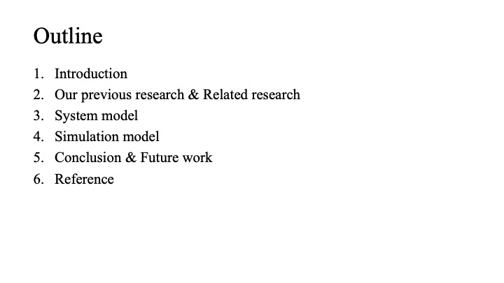 |
Here is the outline of my presentation. |
 ICACT20220184 Slide.03
[Big Slide] ICACT20220184 Slide.03
[Big Slide]
|
Chrome  Click!! Click!! |
 |
Introduction. |
 ICACT20220184 Slide.04
[Big Slide] ICACT20220184 Slide.04
[Big Slide]
|
Chrome  Click!! Click!! |
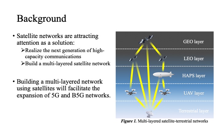 |
So, let me begin by talking about our research background. Satellite networks are attracting attention as a solution to realize the next generation of high-capacity communications by linking the terrestrial networks and the non-terrestrial networks. A single satellite station can cover a very large area of ground, reducing the cost of capital investment for ground stations and facilitating the expansion of the network to rural and developing areas. |
 ICACT20220184 Slide.05
[Big Slide] ICACT20220184 Slide.05
[Big Slide]
|
Chrome  Click!! Click!! |
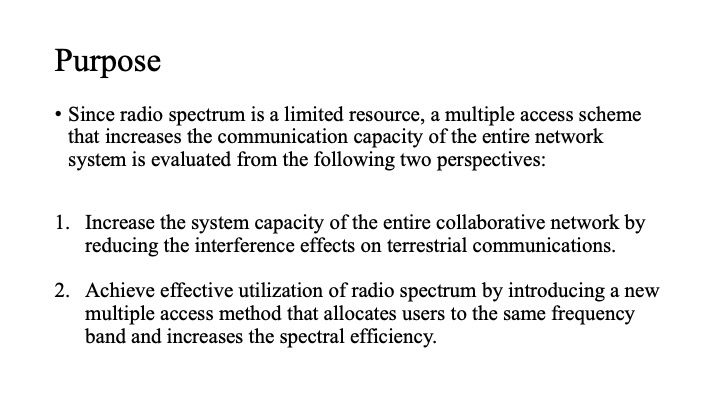 |
Since radio spectrum is a limited resource, a multiple access scheme that increases the communication capacity of the entire network system is evaluated from the two perspectives. The first is to increase the system capacity of the entire collaborative network by reducing the interference effects on terrestrial communications. The second is to achieve effective utilization of radio spectrum by introducing a new multiple access method.
|
 ICACT20220184 Slide.06
[Big Slide] ICACT20220184 Slide.06
[Big Slide]
|
Chrome  Click!! Click!! |
 |
Our previous research & Related research. |
 ICACT20220184 Slide.07
[Big Slide] ICACT20220184 Slide.07
[Big Slide]
|
Chrome  Click!! Click!! |
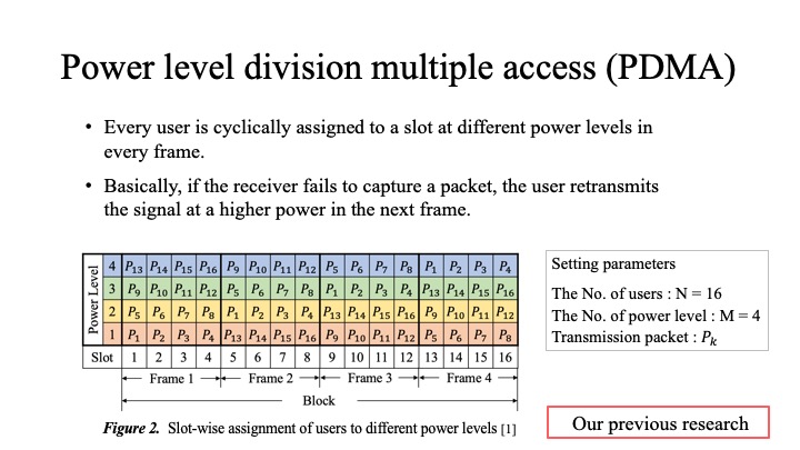 |
The two central technologies of this paper are described in this section. In the PDMA scheme, every user is cyclically assigned to a slot at different power levels in every frame. Users with the highest power levels are given the highest priority for demodulation. If a user with a lower power level fails to demodulate, the probability of success is increased by allocating higher power in the next frame.
|
 ICACT20220184 Slide.08
[Big Slide] ICACT20220184 Slide.08
[Big Slide]
|
Chrome  Click!! Click!! |
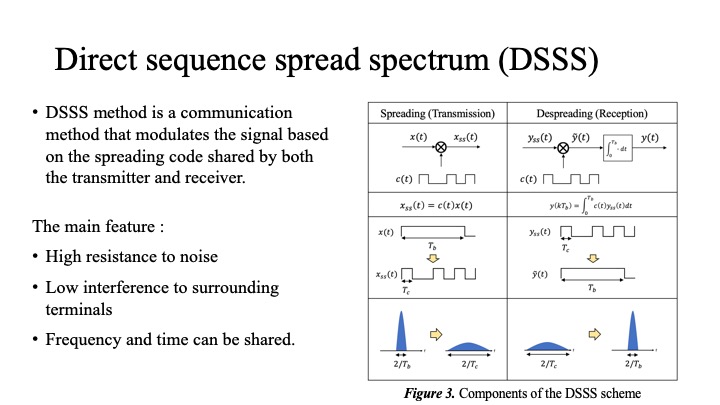 |
DSSS method is a communication method that modulates the signal based on the spreading code shared by both the transmitter and receiver. By applying DSSS processing to the signal, the power spectral density is reduced and becomes closer to noise. This has the advantage of reducing the peak power of the signal and mitigating the interference effects on surrounding users.
|
 ICACT20220184 Slide.09
[Big Slide] ICACT20220184 Slide.09
[Big Slide]
|
Chrome  Click!! Click!! |
 |
System model. |
 ICACT20220184 Slide.10
[Big Slide] ICACT20220184 Slide.10
[Big Slide]
|
Chrome  Click!! Click!! |
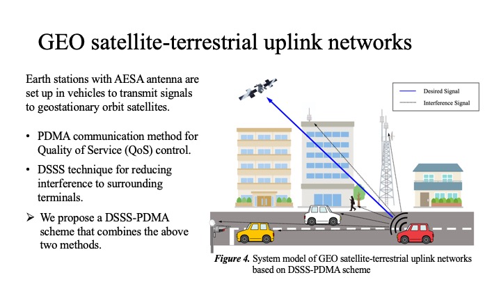 |
In this section, we consider terrestrial users of vehicles with AESA antennas for satellite communications connected to terrestrial 5G networks. The terrestrial users transmit PDMA signals according to the QoS requirements, but the interference effect on the surrounding terminals increases as the power is set higher. Therefore, DSSS process is applied to reduce the interference effect. Our goal is to achieve both QoS control and interference reduction by our proposed DSSS-PDMA scheme.
|
 ICACT20220184 Slide.11
[Big Slide] ICACT20220184 Slide.11
[Big Slide]
|
Chrome  Click!! Click!! |
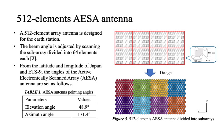 |
In our proposed model, we assume that we will communicate with a high throughput satellite named ETS-9, which is scheduled to be launched in Japan. Therefore, we will first design a five hundred twelve-element array antenna that satisfies the requirements of ETS-9. As shown in Figure 5, the beam angle is adjusted by scanning the sub-array divided into sixty-four elements each. From the latitude and longitude of ETS-9 and Japan, we can calculate the elevation angle and azimuth angle of the ground AESA antenna to be forty-eight point seven degrees and one hundred seventy-one point four degrees, respectively.
|
 ICACT20220184 Slide.12
[Big Slide] ICACT20220184 Slide.12
[Big Slide]
|
Chrome  Click!! Click!! |
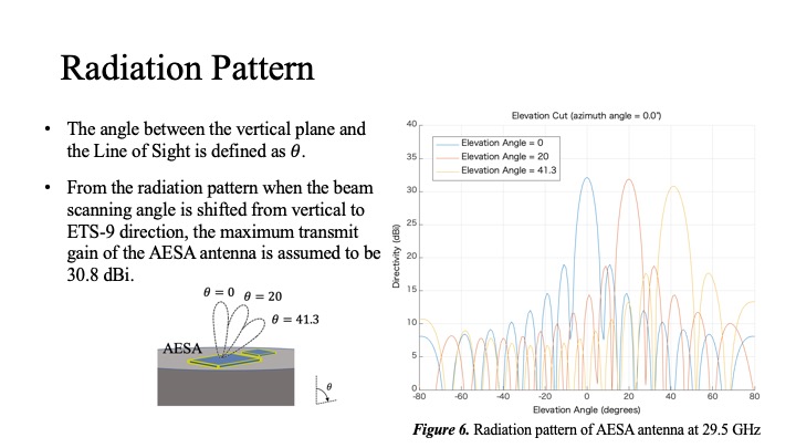 |
Since the AESA antenna will be installed vertically, the beam scanning angle should be set to forty-one point three degrees. The radiation pattern is shown when the beam scanning angle is shifted from vertical to ETS-9 direction. Assuming no pointing loss, the maximum transmit gain of the AESA antenna is calculated to be thirty point eight dBi.
|
 ICACT20220184 Slide.13
[Big Slide] ICACT20220184 Slide.13
[Big Slide]
|
Chrome  Click!! Click!! |
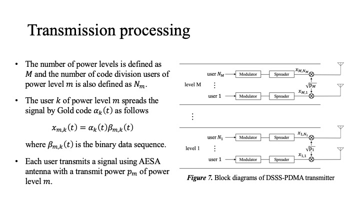 |
The designed antenna is used to perform DSSS-PDMA signal processing to the satellite. At the beginning, each transmitting user is assigned to a higher power level for higher priority users and a lower power level for lower priority users according to QoS requirements. Each user in each power level modulates the signal using a different Gold code and sends the signal to the satellite in line of sight propagation.
|
 ICACT20220184 Slide.14
[Big Slide] ICACT20220184 Slide.14
[Big Slide]
|
Chrome  Click!! Click!! |
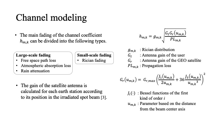 |
Next, the channel coefficients between each user and the satellite station are defined as follows. We adopt free-space loss, atmospheric-absorption loss, and rainfall attenuation for large scale fading, and Rician fading for small scale fading. Among the parameters of the link budget, the receiver gain of the satellite is obtained by calculating the attenuation due to the distance from the beam center axis.
|
 ICACT20220184 Slide.15
[Big Slide] ICACT20220184 Slide.15
[Big Slide]
|
Chrome  Click!! Click!! |
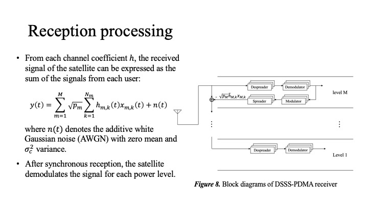 |
The signals from each user are received and composed at the satellite side to form user groups for each power level. As with the SIC method, these user groups are demodulated in order of power level. Now, let's expand the cancellation process part.
|
 ICACT20220184 Slide.16
[Big Slide] ICACT20220184 Slide.16
[Big Slide]
|
Chrome  Click!! Click!! |
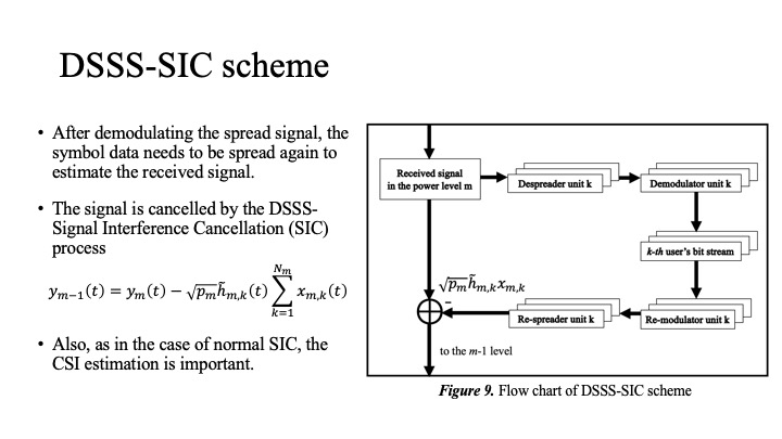 |
In our proposed model, the signal is demodulated using the DSSS-SIC scheme, which adds DSSS to the normal SIC method. First, the received signal is despread following the normal CDMA decoding to demodulate a cluster of users with power level m. Then, the signal of each user is re-modulated and re-spread just like the transmitter to reproduce the received signal. Finally, the received signal is cancelled with all the received signals of power level m. This is repeated for the number of power level divisions.
|
 ICACT20220184 Slide.17
[Big Slide] ICACT20220184 Slide.17
[Big Slide]
|
Chrome  Click!! Click!! |
 |
Simulation model. |
 ICACT20220184 Slide.18
[Big Slide] ICACT20220184 Slide.18
[Big Slide]
|
Chrome  Click!! Click!! |
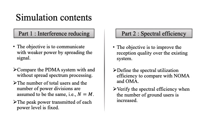 |
The above system model is used to perform the simulation. We evaluate the proposed method in this section based on the two contents mentioned in the Purpose slide. Part 1 is the interference reduction. We compare the PDMA scheme with and without DSSS and verify the relationship between peak power and reception quality. Part 2 is the spectral efficiency. We examine the relationship between spectral efficiency when the number of users is increased, and compare DSSS-PDMA with existing schemes such as NOMA and OMA.
|
 ICACT20220184 Slide.19
[Big Slide] ICACT20220184 Slide.19
[Big Slide]
|
Chrome  Click!! Click!! |
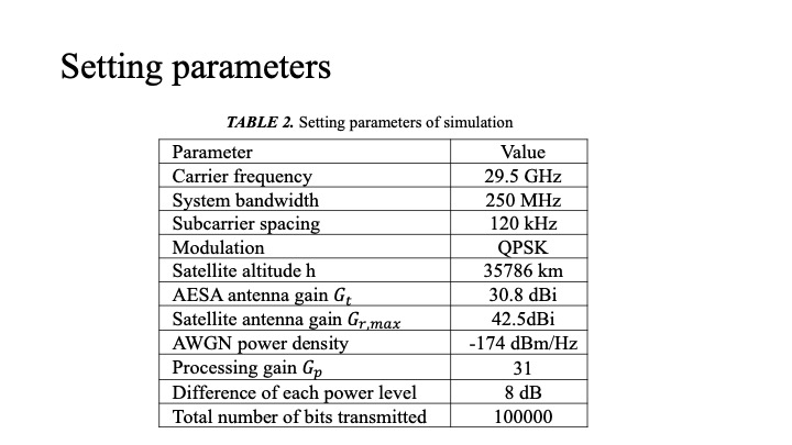 |
The key parameters of our simulations are presented in this table. The carrier frequency is set to twenty-nine point five GHz from the main specifications of the earth station for ETS-9. In the simulation, we first transmit one hundred thousand bits of data and calculate the BER.
|
 ICACT20220184 Slide.20
[Big Slide] ICACT20220184 Slide.20
[Big Slide]
|
Chrome  Click!! Click!! |
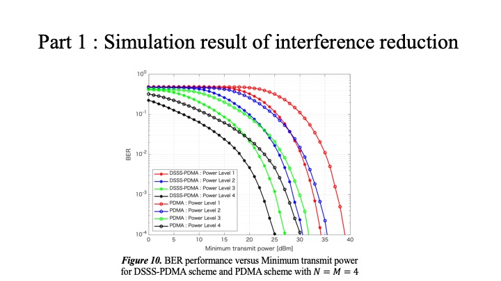 |
The results are shown as DSSS-PDMA for the method with DSSS processing and PDMA for the method without it. Focusing on power level one, the same BER can be achieved with about 5 dB less power for transmission with DSSS processing than without one. In other words, the results mean that the DSSS-PDMA provides higher reception accuracy with lower peak transmit power and less interference power to the surroundings.
|
 ICACT20220184 Slide.21
[Big Slide] ICACT20220184 Slide.21
[Big Slide]
|
Chrome  Click!! Click!! |
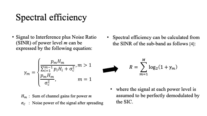 |
The SINR of the signal for a group of users with large power levels has noise component and interference components of signals with smaller power levels. When the signals are demodulated by the DSSS-SIC technique in order and the signals are assumed to be perfectly cancelled, the SINR of users with the lowest power levels have only noise component. The spectral efficiency is calculated from SINR of the sub-band based on Shannon Hartley's theorem.
|
 ICACT20220184 Slide.22
[Big Slide] ICACT20220184 Slide.22
[Big Slide]
|
Chrome  Click!! Click!! |
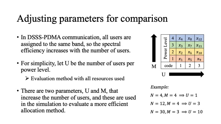 |
In DSSS-PDMA communication, all users are assigned to the same band, so the spectral efficiency increases with the number of users. For simplicity, let U be the number of users per power level. We examine the relationship between the spectral efficiency by increasing the number of users to be assigned, that is, by increasing U and M.
|
 ICACT20220184 Slide.23
[Big Slide] ICACT20220184 Slide.23
[Big Slide]
|
Chrome  Click!! Click!! |
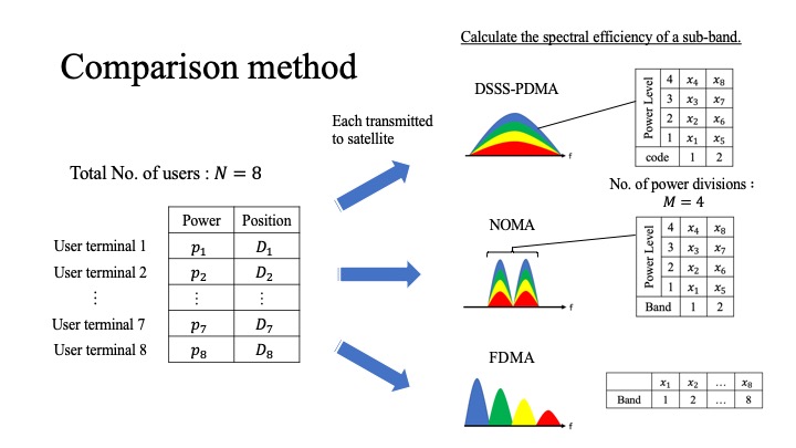 |
Now, we consider FDMA and NOMA schemes for comparison. Due to uplink communications, the received signal from each user can be represented by the same transmission power and channel coefficient. However, FDMA and NOMA schemes do not spread the signal. Since the signal is instead divided by frequency, the spectral efficiency of the sub-band is divided by U for NOMA and by N for FDMA.
|
 ICACT20220184 Slide.24
[Big Slide] ICACT20220184 Slide.24
[Big Slide]
|
Chrome  Click!! Click!! |
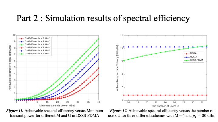 |
Figure. 11 shows the spectral efficiency when the number of power levels M and the number of user U for each power level are increased. It can be seen that the spectral efficiency when M is increased is larger than that when U is increased. Figure. 12 shows the spectral efficiency of FDMA, NOMA, and DSSS-PDMA schemes when U is increased from fifteen to thirty-three, derived from the length of the gold sequences. Since the power level M is fixed, the spectral efficiency of FDMA and NOMA with increasing number of sub-bands does not change. In contrast, the DSSS-PDMA scheme multiplexes the signals in the same bandwidth, so the spectral efficiency increases. In particular, it is greater than the NOMA scheme when U is larger than thirty-one.
|
 ICACT20220184 Slide.25
[Big Slide] ICACT20220184 Slide.25
[Big Slide]
|
Chrome  Click!! Click!! |
 |
Conclusion & Future work. |
 ICACT20220184 Slide.26
[Big Slide] ICACT20220184 Slide.26
[Big Slide]
|
Chrome  Click!! Click!! |
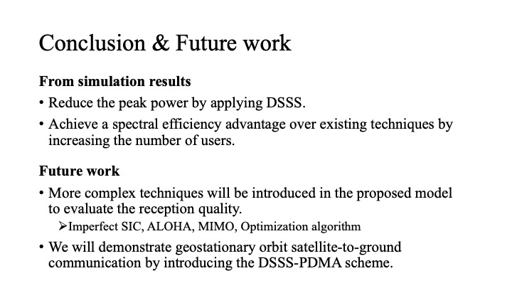 |
Finally, I will summarize our simulation results. By applying the DSSS-PDMA scheme for satellite-terrestrial communication, the transmission peak power can be reduced and a higher spectral efficiency can be achieved than the existing schemes. In our future work, more complex techniques will be introduced in the proposed model to evaluate the reception quality. After further research, we will demonstrate geostationary orbit satellite-terrestrial communication by introducing the DSSS-PDMA scheme.
|
 ICACT20220184 Slide.27
[Big Slide] ICACT20220184 Slide.27
[Big Slide]
|
Chrome  Click!! Click!! |
 |
References. |
 ICACT20220184 Slide.28
[Big Slide] ICACT20220184 Slide.28
[Big Slide]
|
Chrome  Click!! Click!! |
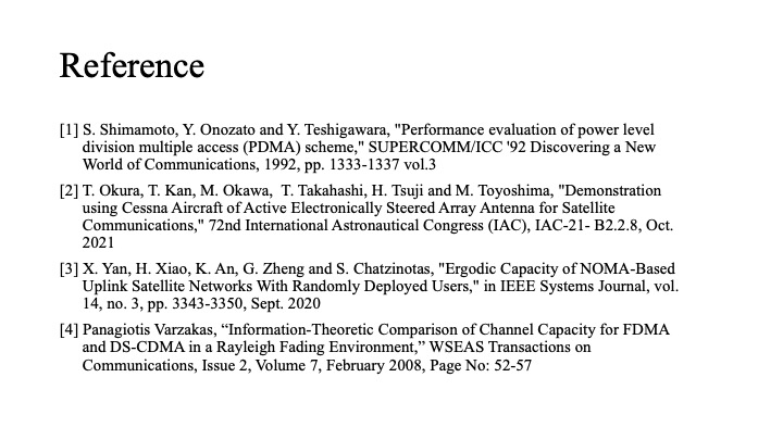 |
These are references. |
 ICACT20220184 Slide.29
[Big Slide] ICACT20220184 Slide.29
[Big Slide]
|
Chrome  Click!! Click!! |
 |
Thank you very much for your attention! |
 ICACT20220184 Slide.30
[Big Slide] ICACT20220184 Slide.30
[Big Slide]
|
Chrome  Click!! Click!! |
 |
안녕하십니까? 김낙구입니다.. 좋은 저녁되고요.. |


