ICACT20240299 Slide.00
[Big Slide] ICACT20240299 Slide.00
[Big Slide]
|
Chrome  Click!! Click!! |
 |
Recently, we scan our map using 16 channel velodyne Lidar. The map on the right side is our lab. We also do simulation for obstacle avoidance experiment. Red path is mobile platform's real path during experiment. For the future, we will design 3D point cloud map to describe more realistic experiment.
|
| ICACT20240299 Slide.01
[Big Slide]
|
Chrome Click!! |
 |
The title is Incorporation of waypoint logic into ROS publish and subscribe mechanism.
|
| ICACT20240299 Slide.02
[Big Slide]
|
Chrome Click!! |
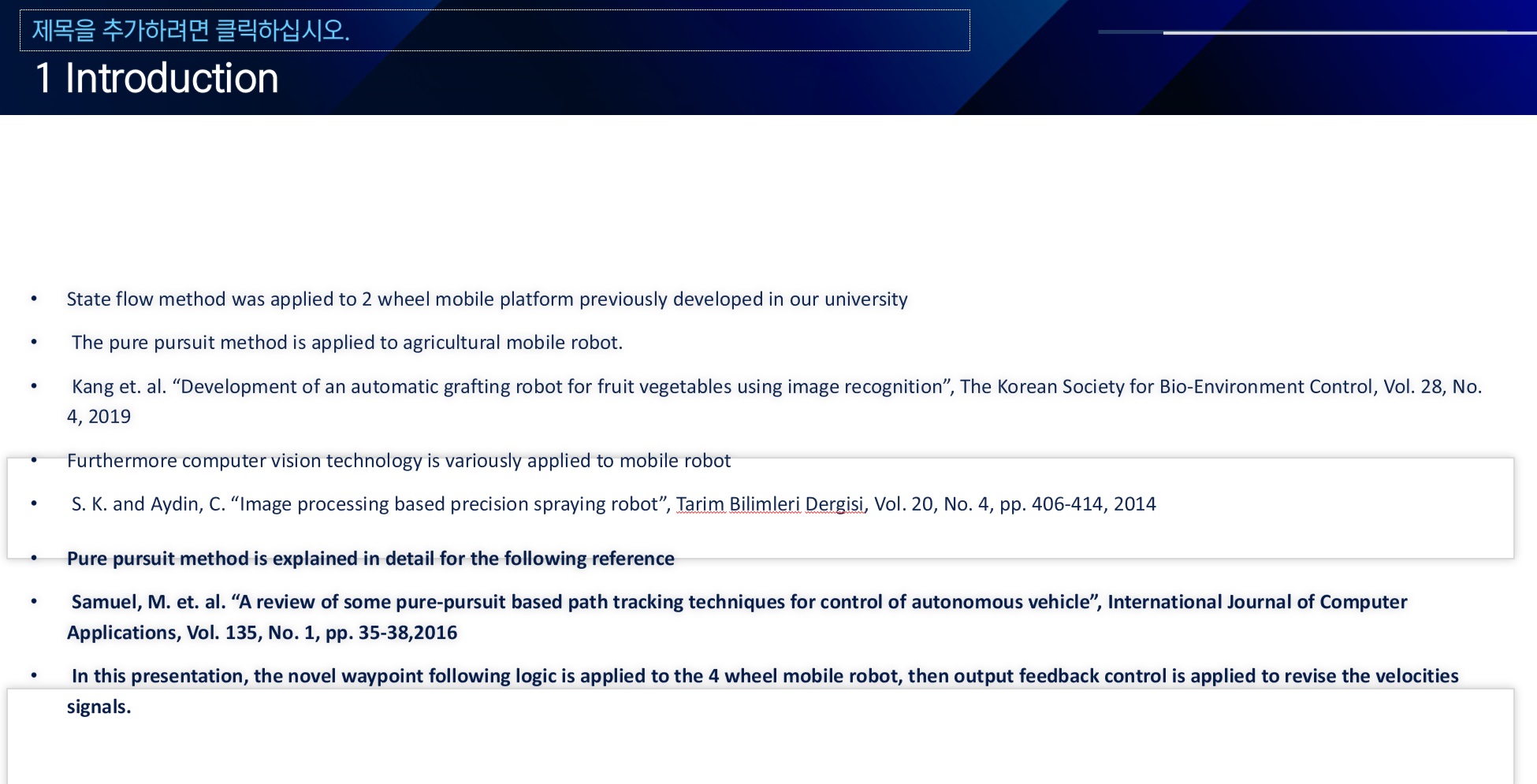 |
We previously use state flow method into 2 wheel mobile plaform. Pure pursuit method is well known waypoint following method. In this presentation we use waypoint following logic, also we will apply output feedback control into mobile robot path following simulator. |
| ICACT20240299 Slide.03
[Big Slide]
|
Chrome Click!! |
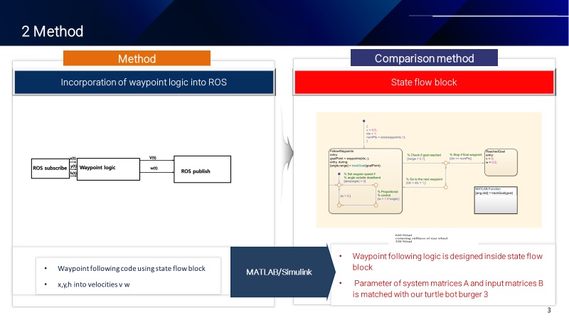 |
This is how we write waypoint following logic in the state flow block in Simulink |
| ICACT20240299 Slide.04
[Big Slide]
|
Chrome Click!! |
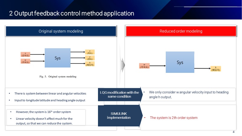 |
In this presenatation we explain how we apply output feedback controller into simulator. Firstly, we consider whole inputs(linear and angular velocities signals), in that case, the system modeling is 12 th order system. Since v is related to x,y,h, each system modeling is 2 th order system. But in this case, it is complex to model. Hence we reduce the model into 2th order system only considering angular velocities signal w and output heading angle h. |
| ICACT20240299 Slide.05
[Big Slide]
|
Chrome Click!! |
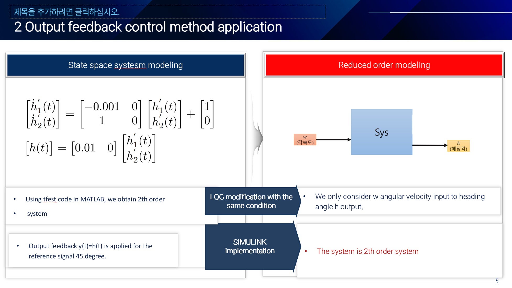 |
After that, we model matrices A,B,C using tfest(transfer estimation) function in MATLAB. Finally, it is possible to model the system by considering angular velocities signal into heading angle. |
| ICACT20240299 Slide.06
[Big Slide]
|
Chrome Click!! |
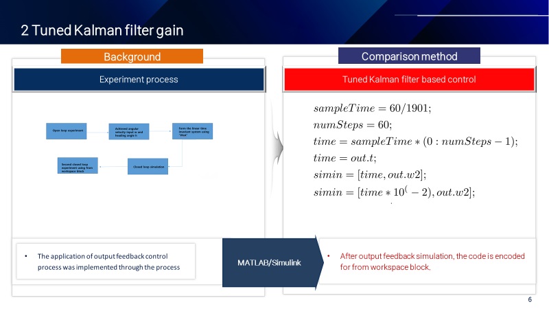 |
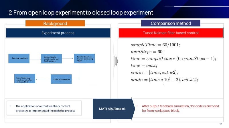
The system's experiment process is on the left side. First of all, we experiment open loop control. If mobile platform in the simulator didn't reach the target point, by putting output feedback simulation, we experiment second closed loop control using revised input from closed loop simulation. In that case, from workspace and to worspace block in the simulink is used. The code on the right side is about code before we used from workspace block in the simulink. |
| ICACT20240299 Slide.07
[Big Slide]
|
Chrome Click!! |
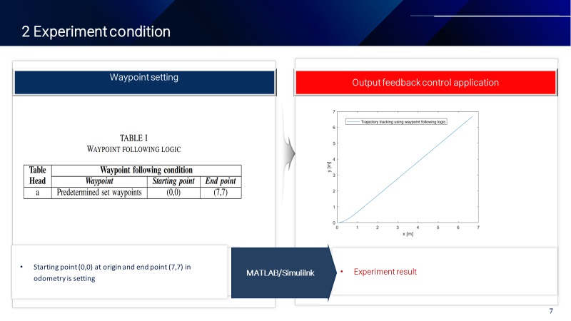 |
So starting point of the experiment is (0,0), and then the end poinst is (7,7). We just verify that the platform in the simulator reaches into (7,7) using revised input from closed loop simulation. |
| ICACT20240299 Slide.08
[Big Slide]
|
Chrome Click!! |
 |
That is second section for future plan. |
| ICACT20240299 Slide.09
[Big Slide]
|
Chrome Click!! |
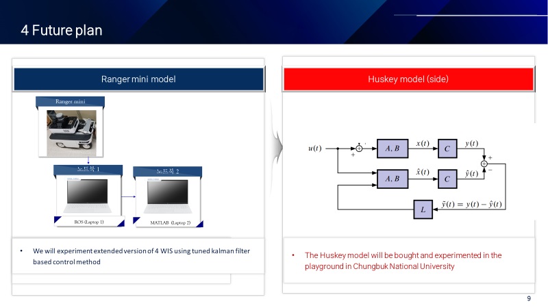 |
We are going to connect MATLAB window laptop into ROS ubuntu laptop. Also ROS ubuntu laptop is connected into 4 in-wheel, and 4 steering motors in the mobile platform. We are also doing closed loop simulation from open loop experiment, then we will achieve revised input from simulation in order to reduce actual path from desired path |
| ICACT20240299 Slide.10
[Big Slide]
|
Chrome Click!! |
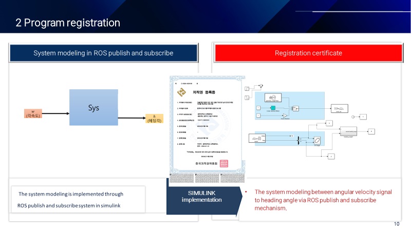 |
To do that, we made the system modeling from angular velocities signal into output heading angle signal. This one is registerd in the program in Chungbuk National University. |
| ICACT20240299 Slide.11
[Big Slide]
|
Chrome Click!! |
 |
We will do same thing in the simulator for the real experiment in uneven path or sliding path. |
| ICACT20240299 Slide.12
[Big Slide]
|
Chrome Click!! |
 |
This one, we will do same thing in the real experiment. |
| ICACT20240299 Slide.14
[Big Slide]
|
Chrome Click!! |
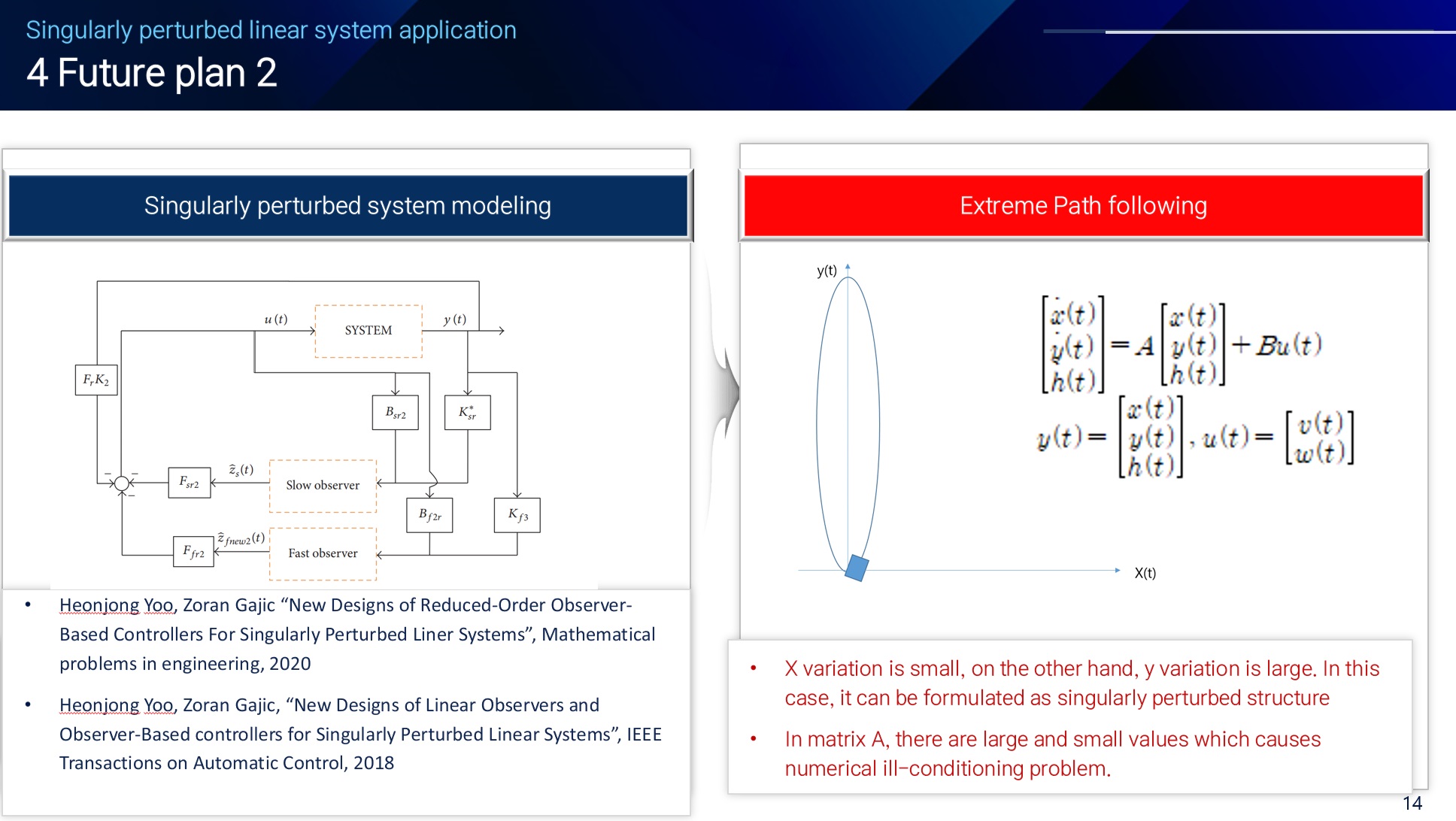 |
Lastly, I majored in control system expecially for the singularly perturbed linear system during my Ph.D. We found that the path on the right side has a characteristic about big y axis variation, small x variation. In this case, it is possible to design singularly perturbed structure by finding epsilon parameters in the system matrix A. We will apply my Ph.D two stage algorithm into the mobile platform path following experiment and get the result in the future. |
| ICACT20240299 Slide.15
[Big Slide]
|
Chrome Click!! |
 |
Thank you for listening this presentation. This is Heonjong Yoo senior researcher at Chungbuk National University |