 |
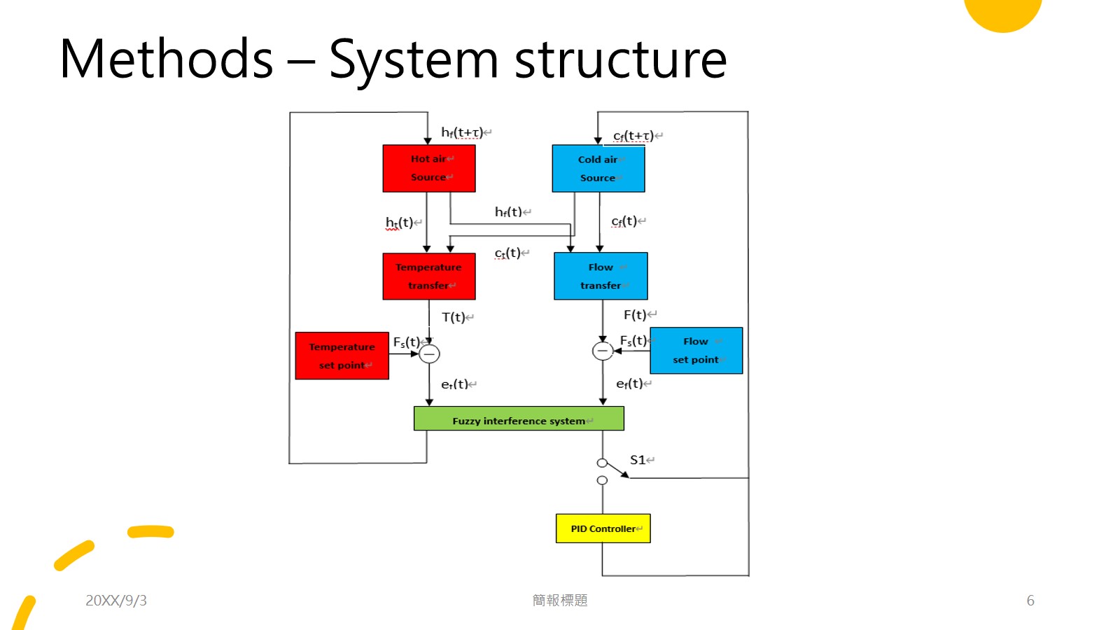
The system block diagram is presented in Fig. 1 which displayed the 2 modes of the controller. One is PID controller, the other is FPID. The modes can be alternated by the switch (S1). There were 2 air flow sources input the phototherapy incubator to adjust the temperature. The hot air flow source output higher temperature air (ht(t)) with the flow speed of hf(t) where t denoted as time. The cold air flow source output lower temperature air (ct(t)) with the flow speed of cf(t). The ht(t) and ct(t) input the temperature transfer block and output sensing temperature, i.e. T(t) as well as hf(t) and cf(t) input the flow transfer block and output sensing flow, i.e. F(t). The temperature and flow setpoints were Ts(t) and Fs(t), respectively. Therefore, in the fussy control mode, we have the errors of temperature (et(t)) and flow (ef(t)), then the errors input the fuzzy interference system (FIS) to compute the next output flows of air sources, i.e. hf(t+ąˇ), and cf(t+ąˇ) where ąˇ is the one step duration of time. If the S1 connected with PID controller, the control mode changed to FPID for computing the next flow cf(t+ąˇ). |
 IEEE/ICACT20230270 Slide.05
[Big Slide]
IEEE/ICACT20230270 Slide.05
[Big Slide]